Scale platform and enclosure
There is a printed case for the station, designed by the project's author: OpenTag-Station on Printables (Creative Commons BY-NC-SA 4.0). You can also build your own base and platform; the second half of this page lists what matters then for weighing accurately and reading tags reliably.
The printed case
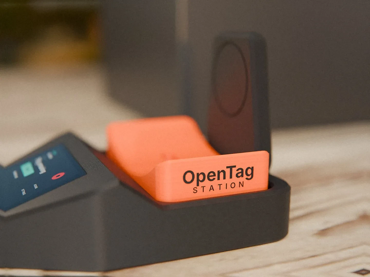
Three parts, about 299 g of filament, no supports. The reader tower at the back holds the NFC module and is also the backstop for the spool. The body is closed, with the screen flush in the top; everything goes in from above, and there is nothing to open underneath. The pockets fit a right-angle USB-C plug and the WT32's side-entry JST plugs. The ring on the tower is 54 mm across and plain, for a logo or a sticker.
The STL files are not in this repository; download them from the Printables page.
| File | Orientation | Notes |
|---|---|---|
scale_body.stl |
Upright, flat floor on the bed | Footprint 154 × 190 mm, 120 mm tall: the bed must be at least 195 mm in Y. No real overhangs; the tunnel roofs are flat bridges of 14 mm or less. |
scale_platform.stl |
Flat side down | The channel underneath is a 14.6 mm bridge. |
nfc_cap.stl |
On its back, as exported |
Print settings: PLA or PETG, 0.2 mm layers, 3 to 4 walls, 15 % gyroid infill, no supports. The files are exported in print orientation; import them as they are.
Hardware for the case, in addition to the parts list:
- 2 × M5 nuts and 2 × M5 × 12 button-head screws (ISO 7380, head height 2.8 mm or less)
- 2 × M5 × 16 cap screws
- 2 × M2.5 × 10 screws with nuts
- 4 × 12 mm stick-on rubber feet (or print your own in TPU)
- A USB-C panel-mount cable and a right-angle USB-C plug
Assembly
- Load cell. Slide two M5 nuts into the channel at the end of the load-cell pedestal (left end, reachable through the platform bay). Set the cell on the pedestal with the wires toward the left, then screw the button-head screws down into the nuts.
- USB-C panel cable. Put the flange in the rear recess and pass the plug end through into the bay. Secure it with the two M2.5 screws and nuts; the hex traps open into the bay. Route it through the right tunnel and the load-cell wires through the left tunnel. Both come out in the cavity under the screen.
- NAU7802. Place it between the locator lugs on the cavity floor, under the screen.
- NFC reader. Drop it into the tower slot from the top. Its wires go down the shaft inside the tower and come out into the platform bay. Run them across the bay into the left or right tunnel with the other cables, then press the cap on.
- Platform. Put it on the cell's free end with the two M5 × 16 screws through the oblong pocket. It sits straight on the cell, with no spacer.
- Screen. Orientation matters, because the cavity has pockets for the plugs. Seen from the front, the WT32's USB-C end goes on the left and the edge with the I/O, DEBUG and SPK JST connectors at the top, toward the back. The right-angle USB-C plug fits untrimmed in the front-left corner; the JST plugs and their wire bend have a pocket under the back edge. Plug in the cables, then press the WT32 straight down until the glass is flush with the top. Four 0.2 mm friction ribs on the side walls hold it, and it rests on a 3 mm ledge all around.
- Feet. Stick the four rubber feet under the body.
To remove the screen, use a small suction cup of the phone-repair kind. If the screen is loose on your print, two thin strips of double-sided foam tape on the ledge fix it. If the picture comes up upside down for the way the board sits, turn it in the browser: Settings → Display → Screen orientation, see Display.
Put the spool on with its tagged flange facing the back tower, and slide it in from the front until it touches.
Build your own base and platform
If you do not print the case, the rules below apply. They also explain why the case is shaped the way it is.
Mount the load cell
The YZC-133 is a bar that bends very slightly under load. One end is fixed to the base, the other end carries the platform. Use the mounting drawing that came with your cell for hole positions and screw sizes.
- Find the fixed end, the load end and the arrow that shows the direction of force.
- Screw the fixed end to a rigid base. Put a spacer between cell and base so the rest of the bar hangs free.
- Screw the platform to the load end, again with a spacer. Do not clamp both ends to the same part.
- Check that the platform touches nothing but the load cell: not the case, not a cable, not the NFC module. Press gently on each corner to be sure.
- Fix the load-cell cable to the base and leave a relaxed loop towards the cell. A tight cable acts as a spring and shifts the zero point.
- Make the platform large and level enough that a spool cannot tip or hang over an edge.
Place the NFC reader
The antenna is on the NFC module itself.
- The tag on the spool must end up close to the module when the spool sits on the platform. Try the reading distance with your spool and tag before you fix anything in place.
- Keep metal away from the antenna and from the tag: the load cell, screws, metal plates. Metal next to the antenna can stop tags from being read.
- If the module is mounted on the moving platform, its cable must not pull on the platform.
- Test with the enclosure closed. A tag that reads on the open bench may not read in the case.
Check your build
- With the platform empty, tare and calibrate.
- Put the known weight on the middle of the platform, then near each edge. The readings should agree closely.
- Remove the weight. The reading returns to zero.
- Place a tagged spool the way you will use it. The station identifies it within a few seconds.
How accurate your scale is depends on your build.
Overload
The station reports Scale overload detected. Remove weight and retry. when the weight is more
than the cell's capacity times the overload setting.
By default that is above 5500 g for the 5 kg cell and above 2200 g for the 2 kg cell.
The same message appears when the load-cell signal is out of range, whatever the weight,
for example with a loose or swapped cell wire.
This is only a message. It does not protect the cell: do not load it beyond its rated capacity.
If something goes wrong
| What you see | What it means | What to do |
|---|---|---|
| The reading changes when you press on the case | The platform touches the case. | Find the contact point and make clearance. |
| Zero shifts when a cable moves | The cable pulls on the platform. | Fix the cable to the base and leave slack. |
| Different readings at the edges of the platform | The mounting is not rigid, or the load is off-centre. | Tighten the screws; stiffen base and platform. |
| The reading does not return to zero | Something binds, a screw is loose, or the cell was overloaded. | Check clearance and screws. |
| Tags stop reading once the case is closed | Metal near the antenna, or the tag is too far away. | Move the reader; test with the case closed. |